So, here’s something I’ve been meaning to write up for almost a year: how to build an Arduino-powered interface to get data from any real-world, analog sensor into an iOS device using the mic pin on the 1/8-inch headphone jack. Meaning: a simple, cross-platform solution for data acquisition on your smartphone with *no* proprietary hardware or jail-breaking required. Sound awesome? It is.
Of course, this solution is about a year old (demo’d at Maker Faire in September 2010) pales in comparison to, say, the recently announced Android Open Accessory initiative and the Android Device Kit. Also, there are similar solutions out there that are better-designed and better-performing. (See, for example, Project HiJack by a team of researchers at the University of Michigan.) In the end, I put this page together to show how to do this data-through-headphones thing using stuff DIYers have lying around, like an Arduino.
It’s stupid easy to implement once you have all the pieces of the puzzle. In some ways, though, it’s stupid stupid. Among the known shortcomings: As microcontrollers go, the Arduino may not be the best suited to the function is serves here — overmatched in some ways, under-matched in others. Moreover, this solution could stand better circuitry for signal and power conditioning, a solid technique to handle multiple sensors chained together, and probably countless other improvements.
I collaborated with my friend Sean Montgomery, a neuroscientist-turned-artist/hacker, to get this simple solution underway. We accept zero responsibility for whatever godawful thing you might do to your device after reading this. That said, here’s how you do it.
Rationale
In this toy example, we want to collect data from an off-the-shelf heart rate monitor from Polar Electronics and display it on an iPod Touch. This is a super simple application for demo purposes. I wanted a basic example that doesn’t require you to do much in the way of signal conditioning to get your sensor data in play. Of course, there’s nothing to stop us from collecting data from any sensor that puts out a continuous variable voltage, in other words an analog signal: a photoresistor, a range-finder, a galvanic skin response sensor, etc. And there’s nothing to stop us from reading that data into and iPad or iPhone, or any Android device that has a 4-conductor, TRRS (tip-ring-ring-sleeve) 1/8-inch headphone jack.
What You Need
- an iOS device (iPod Touch 2G and up, iPhone or iPad)
- a sensor like the WearLink transmitter/receiver
- an Arduino microcontroller
- a solderless breadboard or perf board
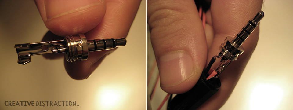
- a male TRRS jack or pair of mic’d or remote-control headphones you don’t mid destroying
- jumper wires or wire and solder
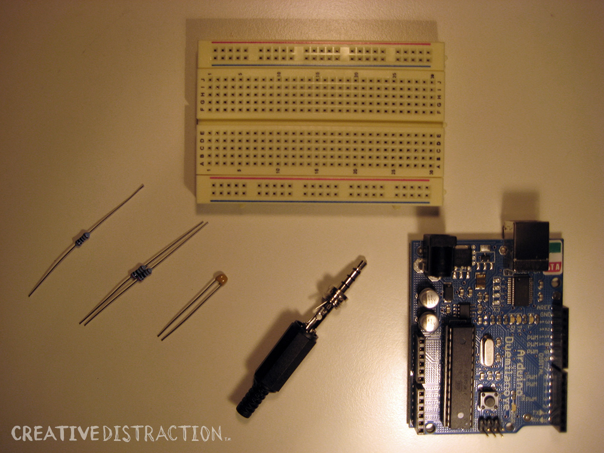
- various resistors and capacitors (see schematics)
How It Works
We use a well-established analog-to-digital signal processing technique called Frequency Shift Keying (FSK), wherein data bits are communicated by modulation and demodulation — basically encoding data in specific audio tones sent over an audio channel. Some of you oldsters might remember the weird sounds emanating from the early telephone modems? That was FSK. (I’m pretty sure R2D2 uses FSK, too. Decoding that is on my bucket list.)
Using compatible FSK libraries on both the Arduino side and the iOS side, we can actually accomplish bi-directional communication between our sensor rig and our mobile device. The Arduino gives us the onboard computing power to be able to both write and read data using FSK. The example in this demo keeps things simple by establishing a uni-directional connection, sending data from the heart rate sensor to the iPod only. Still, we need to do FSK on both the Arduino side (modulation, or encoding the sensor data as audio) and the iOS side (demodulation, or decoding the audio as data). So, all the raw materials are here for a bi-directional connection and whatever bat-shit crazy application you can dream up for using it.
In particular, we use the following open-source FSK libraries:
- arms22’s SoftModem library for Arduino
- Perceptive Development’s SerialModem for iPhone
These libraries are both setup to encode data in shifts between audio frequencies 4000Hz (LOW) and 8000Hz (HIGH). While you will see claims that these softwares can achieve baud rates of 1200bps, or the equivalent of 150 ASCII text characters per second, empirical testing shows that the actual data throughput we achieve using this approach and the above hardware is much lower: more like 50bps, or 6-7 ASCII characters per second. Still, that’s plenty of bandwidth for a basic heart rate monitor, and probably enough for a number of sensor applications that use 8-bit resolution (i.e. 256 possible values).
Putting It All Together
First, you need the sensor, Arduino and supporting circuitry for gathering data. For this demo, we’re keeping it simple and using off-the-shelf electronics from Polar. I’m wearing their WearLink strap, which has two electrodes that pick up the electrical signal generated by my heartbeat, transmit it wirelessly to a receiver chip on the breadboard, which then feeds it into the Arduino. You can reference Sean’s site for schematics of the transmitter/receiver, where to buy them, and a great writeup on EKG in general.
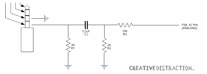
You will also need to build some simple circuitry and load some code onto the Arduino. Although I really like the Arduino Mini for this application, the quickest implementation uses a Duemilanove (or similar) board with a built-in DC socket for our 9V battery and a 3.3.V power line to drive the receiver chip (which will go crazy, incidentally, if supplied with too much power). Here is the setup:
The Arduino code for the heart rate monitor can be super simple: In the loop, you just monitor for a HIGH signal on the pin connected to the receiver chip, and if there is one, simply send an ASCII number “1”, via FSK modulation (i.e. the “modem”). Bingo. Something like:
<br></br>#include <SoftModem.h><br></br>#include <ctype.h><br></br>SoftModem modem;<br></br>int ledPin = 13;<br></br>int heartPin = 4;<br></br>int heartState = LOW;<br></br>void setup () {<br></br> modem.begin();<br></br>}<br></br>void loop () {<br></br> heartState = digitalRead(heartPin);<br></br> if (heartState == LOW) {<br></br> // Do nothing...<br></br> } else {<br></br> // We have a heart beat:<br></br> char h = '1';<br></br> modem.write(h);<br></br> digitalWrite(ledPin, HIGH);<br></br> delay(100);<br></br> digitalWrite(ledPin, LOW);<br></br> }<br></br>}<br></br>
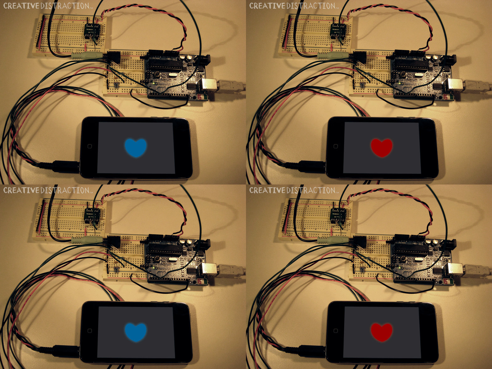
Finally, you need an iOS app. Here, the best thing to do is download the iPhone Hacks book’s source code from Perceptive Development, especially the SerialModem example that connects an external keyboard to the iPhone. Building on Perceptive’s base classes for doing FSK, you can make your application do whatever you want upon receiving new data. In our case, we simply swap the image in our view controller depending on whether or not an ASCII “1” was received (i.e. heartbeat was detected).
That’s it! Like I said, stupid easy. And stupid stupid.


